
Primer
As most car enthusiasts know, automobiles have been increasing in technical complexity over the years. It used to be that a car was pretty much a mechanical device that people with some degree of mechanical aptitude and a few basic tools could perform most of the service and repair tasks. Modern cars possess more qualities of a computer than anyone would have guessed 30 years ago. It is not uncommon for cars to have multiple computer systems.
My first few cars were very basic vehicles. No computers, that's for sure. In fact, the most complex piece of electronics was probably the electronic tachometer. The 1980 DL had a few simple electronic modules to control the wiper delay, but no fuel injection and no electronic ignition.
Quite a number of years ago, my wife and I purchased a 1989 740 Turbo. Now this car was a quantum leap in technology from anything I had owned previously. For those of you not familiar with the Turbo of this era, it is loaded with techno-bobbles of every description. I recently described it as a bit of a techno-mechanical liability due to the number of extras. In the beginning, I found the car to be very intimidating and would never have contemplated tearing into the workings of the car. Virtually everything done to the car was done by the dealership. As time wore on, we became more comfortable with it's technical complexity and I started doing more and more of the work myself.
If you are not overly inclined to dig into your newer car yourself, you may still wish to have some working knowledge of the systems even if you plan to have a shop work on your car. As most Volvo owners know, it pays to choose a shop that knows the cars thoroughly. Specialising in one brand of automobile allows the shop to become experts with that brand. If you work on Chryslers day in and day out, chances are that most systems of a Volvo will appear fairly foreign.
One thing I can state is that you can never have enough tools. It is sometimes hard to justify purchasing tools, but in most cases you need only use them a few times before they have returned their value.
Clubs can be a wealth of technical information - which is one of the reasons that people belong. If your grapple-grommet is worn out, chances are that at least a dozen people in a club have already replaced their grapple-grommet. Sometimes, all you need is a few guiding points and a bit of encouragement to help you through a repair.
There are good forums on the internet that can also be a wealth of information. These are self-regulating bulletin boards that allow enthusiasts to exchange information with others. Some of the data bases are huge. You must remember that there can be erroneous information, but if you investigate carefully and weigh all of the opinions and use your good judgement, lots of useful information can be gained from these forums.
My first courageous repair on the 740 was the replacement of the timing belt and water pump in 1999. It was pretty much like working on a 240, just a bit less space to work in. For this task, I bought a Volvo crankshaft counterhold. Perhaps some may argue that the tool is unnecessary, but I have now used it twice, and may well use it many more times in the future.
The most recent venture into the car occurred in April 2003. My wife was driving home from work one Saturday when the engine gods became angry and blessed a curse on the B230FT. After having the car towed home (always a sad site) I took a chance on opening the valve cover and found what appeared to be a broken exhaust valve spring. The end result is that after a few hours worth of work and a supply of parts, had the car back on the road. Of course, it took nine days to gather the hours together. The motivation was mostly one of economics, though it's always great to gain the experience and confidence. The good news is that the car has been working flawlessly ever since.
I have found in the past that performing a repair usually gains one considerable insight and experience. The next time the operation in performed, it is likely to take considerably less time. If too much time elapses between the operations, some of these memories can fade and then there is a bit of a relearning process on the next installment. For this reason, I decided to document the operation so that I could store it away for the next time I happen to need to get back into the same area. Once the whole ordeal was over, Gregg Morris requested that I write about the repair for submission to the newsletter. A good part of the writing had already been done, so very little else was needed. The article appeared in the late summer 2003 newsletter and has now been added to the Club website with this primer. It was intended first and foremost to be a how-to article, so its entertainment value is quite low.
A few pictures are also included in this article.
ARTICLE
Patient Symptoms
The car was towed home after losing most of its power, making a distinct ticking noise, running very unevenly and producing a wavering manifold pressure. After inspection of the camshaft and followers, it was quickly determined that follower for the number 3 exhaust valve was not in contact with the base circle of that cam. The follower could be depressed slightly with moderate pressure. The diagnosis was that of a broken valve spring.
For those of you unfamiliar with the layout of the B230 valve train, here is a description. The valve stems and springs are hidden directly under the large-diameter (37 mm) followers. The followers move up and down in guides cast into the cylinder head and normally sit with the cam contact flats up clear of the casting. The camshaft rotates on bearings cast directly into the head and press down on the followers. Valve adjustment is accomplished by interchangeable disks of different thicknesses held in a recessed area on the top of each of the followers. On the B230FT, the distributor is located at the rear of the head and is driven directly from the end of the camshaft. Since access to the springs is possible only by removal of the followers, the camshaft must first be removed. As our timing belt was half way through its life, I decided to replace that at the same time.
Disassembly
Once the cam cover is off, there are three basic steps to removing the camshaft on the B230FT: remove the distributor, remove the timing belt from the camshaft timing wheel, remove the five camshaft bearing shells.
Cam Cover
Remove the ignition leads from the spark plugs and distributor. Keep the leads attached to the holder to keep them in order. Ignition lead order on the distributor cap, looking left to right, is 4-3-1-2. Loosen and remove the ten nuts holding the cover on. I chose to measure the valve clearance in case it was in need of adjustment. Changing the shims if very simple to do once the cam has been removed.
Accessory Drive Belts
Removing the timing belt on these engines is not a five minute job. [It should be mentioned at this point that the operation of removing the camshaft can be performed by simply slipping the belt off the camshaft timing wheel and reusing the old belt. This was not the route that I chose.] Since the belt is hidden inside the belt covers and behind the crankshaft damper all of which is behind the accessory drive belts, the first step is to remove the drive belts. The power steering pump, alternator and air conditioning compressor all have their own belt tension adjustment. The latter two are easily found and can be slackened off with a 10 mm socket or spanner. The power steering pump adjustment is much more difficult to access. My decision was to remove the fan and fan shroud to gain easier access to this tensioner. It is also accessible from below by removing the belly pan, though it is debatable which is less awkward. As with many operations on these cars, it is useful to have a long arm with two hands and five or more elbows. The belts come off in the following order and should be marked if you are not familiar with their identification: air conditioning, alternator, power steering.
Crankshaft Damper
Once the accessory belts are out of the way, the crankshaft damper can be removed. This can be a long, tedious step for a number of reasons. First of all, the nut must be removed. A 24 mm socket fits the nut. If you choose to use a long bar, you will need to keep the crankshaft from rotating. I am fortunate enough to have a crankshaft counterhold (5284) to lock the damper in place. This tool engages in the slots in the damper and bolts on to the belt tensioner bolt. There has also been discussion about using an impact wrench to loosen the nut. When I first changed the timing belt I had neither impact wrench nor compressor, so the decision to buy a counterhold was quite simple. I ordered it through Docksteader motors and received it within a week or so. It turned out that removing the nut was the simple part. The difficulty was in removing the damper assembly. A layer of rust held the damper fast to the crankshaft. It was only with the help of a seasoned Volvo mechanic that it was eventually removed.
Timing Belt Covers
Both the upper and lower timing belt covers can now be removed along with their associated hardware.
Timing Belt
Rotate the engine so that the timing marks on all three shafts are aligned on their index. Loosen the nut for the tensioner and pull on the belt to retract the tensioner. Insert a 3 mm drill bit or similar object into the hole which will be exposed once the tensioner spring has been depressed sufficiently. This enables the tensioner to be removed and stored in the compressed state. The belt can now be removed from the engine.
Distributor
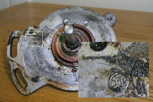
The distributor is driven from the back end of the camshaft through an offset key similar to that used on the front-mounted distributor. Mark the angular position of the distributor relative to the flat surface on the top of the head.
Once the distributor is out you will be able to see this mark on the bottom of the distributor as shown in this photo. (38 kB)
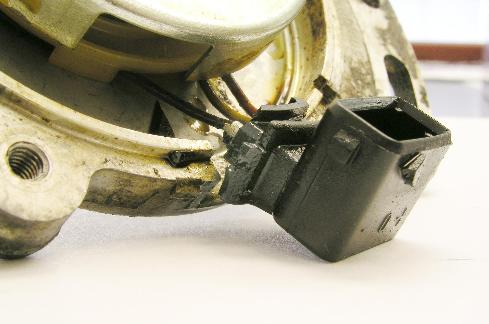
This is a close-up of the broken hall effect connector. (28 kB) (28 kB)
This is another close-up of the broken hall effect connector. (24 kB) (24 kB)
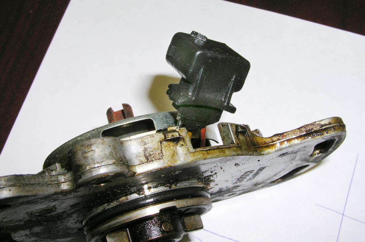
This is the edge of the distributor. The main O-ring seal is visible as is the pin that holds the drive key on the shaft. (122 kB) (122 kB)
Before removing the distributor, it is necessary to remove the distributor cap and rotor. Three machine screws secure the cap. These are a little awkward to access. The rotor is simply pulled off the shaft. Use a 10 mm spanner to loosen and remove the two bolt securing the distributor to the head. The distributor can then be slid out of the back of the head. Ours was well baked into position and took considerable coaxing to get it to move. Once loose, the hall sensor leads can be unplugged from distributor. The plastic connector on the distributor normally becomes brittle after many years of baking, so don't be surprised if this breaks or is already broken. It is available separately and is not expensive. When changing this connector block, be very carefully not to break the very fragile wires. This can easily drive up the cost of repair.
Cam Bearings
The last step is to remove the bearing caps securing the five cam bearings. The Volvo manual recommends a camshaft depressor to hold it in place. If you don't have one of these handy, make sure that you undo the ten bolts only a bit at a time to avoid placing stress on the bearings. Pull the front plastic cover forward slightly to clear the camshaft and pull the camshaft carefully up out of the bearings.
Further Assessment
Now that the camshaft is out of the way, the followers can be lifted out of the way to expose the springs, keepers and valve stems. The simplest way to lift the followers up is with a magnet. Take care not to nick any surface of the follower or shim. For example, dropping them on a concrete floor would be a bad thing! The suspect valve was found to be totally free to move up and down and around. If the valve stem had been bent in the ordeal, it would most certainly be binding in the guide at some point.
Decisions, Decisions
At this point I had to make a decision on whether to simply replace the broken valve spring or replace all of them. There was also a chance of some internal damage due to valve and piston collision which could only be seen by removing the head or sending a very small camera in through the spark plug hole. The clearance between the piston and valve is adequately maintained as long as the valve follows the cam. In this case, the spring was sufficient to keep the valve in contact with the cam during maximum lift so, in theory, the valve would stay out of reach of the piston. However, at higher revs there is no guarantee that the valve will follow the cam completely going over the peak of the lift. Luckily, this engine was not running at super high speed when the failure took place. Although there was substantial noise from the valve train, this could simply have been the valve contacting the seat or the follower landing on the back side of the cam lobe.
There was no guarantee of no internal damage. On the other hand, there was not sufficient evidence of pending cascading catastrophic failure to warrant spending the time and money (a gasket kit is rather costly) on removing the cylinder head. In the end, the decision was to simply replace all springs with the head in place. Apparently, there was a Technical Service Bulletin about replacing the valve springs with an upgraded model, so replacement of all springs was warranted.
If you have had troubles with leakage of oil around the other front shaft seals and have been waiting for the right time to replace them, this would be it.
Valve Spring Replacement
When removing the followers, make certain to label them so that they are not mixed up. They should not be interchanged. Inside the follower, or perhaps still on the stem of the valve, you will find the remainders of the once soft rubber bumpers that are used to quieten the valve train. These are inexpensive and should all be replaced. They become hard through years of baking and become ineffective. It is common to find them cracked or in several pieces.
I chose to keep the followers in position as much as possible to minimise the risk of dropping small parts down into the area of the springs. While working on the springs I stuffed a rolled up part of my favourite old swim cap down between the spring and the head to avoid losing the keepers down into the depths of the engine. It worked. We didn't lose a single one.
There are two tricks to removing the springs. First of all, you must make certain that valves are not dropped into the cylinder. That would be considered a really bad thing. If there was any previous doubt about taking the head off, that doubt would then be removed. I have an air compressor and so chose to purchase a compression tester that conveniently had a standard air fitting on the flexible hose. It was a simply matter of removing the check valve from the engine end of the hose and it was ready to pressurise the cylinder being worked on thus holding both valves closed. I used about 150 lb/in 2 because I had it available. Considerably less could do. For added safety, I turned the engine to place the piston at TDC. The counterhold kept the engine from flipping over. Since the valve retainers may well be frozen solid from years of baking, affected retainers can be loosened by hitting them off centre with a brass punch.
The second trick is to compress the spring completely to remove the retainers. I was fortunate enough to borrow a top-side-only compressor that was a simple lever with a cylindrical pusher attached to the level by a pin. This lever was hooked under a steel rod secured to the head and running the length of the engine. This tool was designed to be generic, and it did do the job, but was not optimum.
A similar tool can be fabricated at home. Rhys Kent suggested that one could be made from a ring and two pieces of band iron. A wooden lever can be used to push down on this assembly once a fulcrum has been fashioned with rope and fastened to some part of the engine. I fully intend to design my own special tool, some year when I have lots of idle time, probably after retirement, for the next time I have to perform this operation. It would be really convenient to not have to hold the lever while fishing the retainers in and out. It turned out that it was a two person job, two hands to compress the spring and two to replace the keepers. I was fortunate enough to have my wife come out and lend a hand with this. Her incentive was to get her car back on the road without further delay.
With the springs pressed fully, lift out the two halves of the valve keepers. Release the compression of the spring. The spring and its upper seat can be lifted out. The replacement spring from Volvo comes with new upper and lower spring seats. I left the intake seats in place to avoid removing the stem seals. The exhaust stems do not use seals as they would probably melt from the valve temperature. Drop in the new parts and compress the spring. The keepers can be greased on the inside so that they will stick to the valve stem. To aid in dropping them in place, place some grease on a long flat blade screwdriver and stick the keepers into the grease. This operation can be done in a few minutes. However, our first one took about a half hour of cursing and swearing. This points out the importance of fully compressing the spring.
Reassembly
As is often said in manuals, "assembly is a straightforward reversal of disassembly." However, there are a number of tricks.
Everything that can be cleaned should be cleaned. I took the time to clean the camshaft and valve cover thoroughly. I elected to polish the seal surface on the shaft to help ensure a good seal and to reduce the risk of seal damage from installation onto a rough or dirty part of the shaft.
I also took the time to suck out all standing oil in the head ponds using a small medicine syringe. Best not to reuse it for medicine once done. Clean the camshaft bearing thoroughly. Since my timing belt was completely out, I could turn the intermediate shaft by hand allowing some oil to ooze up through the oil ports in the bearings in the unlikely event that some foreign substance had been dropped into the ports.
Rubber Dampers
The rubber dampers are pressed onto the top ends of the valve guides with the square end down and the tapered end up. These help quieten the valve train noise and have a very limited lifespan. They are very inexpensive. Some of ours were literally just small crumbs.
Followers
The followers can be dropped into place, making certain that they go into their original home. Each follower should be oiled as it is dropped into the guide in the head.
Installing the Camshaft
There is a reason that the camshaft is easiest removed and replaced with the engine in TDC, though it matters very little which of the two angles. One and four are chosen to be TDC to aid in setting the valve timing. If you look down the length of the camshaft, you will notice that all of the lobes, roughly speaking, fall in one of four lines forming an "X". To avoid having to full depress a valve when reassembling an engine, it makes sense to place the cam with the lobes looking like an "X" rather than looking like a "plus". No matter which way you place the "X" it will correspond to the engine at TDC-BDC. The way to assure cylinder 1 at TDC ignition, you want to chose the lobes on cylinder 1 to be pointing up in a "V". This will have cylinder 3 in "<", 4 in "^" and 2 in "<".
Cover the cam bearings and camshaft bearing journals with new oil. Normally, a depressing tool is used to hold the cam down while replacing the bearing caps. I found that it was sufficient to simply press the shaft down while replacing the bearing caps. The caps are all numbered. It is quite important to tighten the bearing caps evenly to avoid stressing the bearings with a tilted camshaft. This is precisely why the press tool 5021 was invented. Finally, tighten the caps to 20 N-m (14 ft-lbs). Temporarily install the timing wheel and verify that the shaft rotates freely. The factory manual recommends applying a sealant (part number 1161027-6) to the under sides of cap numbers 1 and 5.
Now is a good time to check the valve clearance if you haven't already done so.
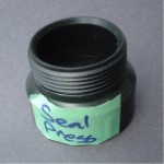
A new shaft seal should be installed on the front of the camshaft. I found the perfect press tool. It so happens to be a 1.5 " ABS plumbing piece that I found in my plumbing drawer. It has a circular lip of about 43 mm and fits perfectly around the outside of the seal body. I think the part is something that would be used under the kitchen sink and I'm sure you could find one from your local building supply store for about one or two dollars. Take the seal with you when you go.
Put the front cover back in place making sure that its locating dowels fall correctly into the holes. Place the timing wheel on the front of the shaft, install the bolt and washer and tighten to 50 N-m (35 ft-lb) using a counterhold to keep the shaft from rotating. If you're like me and don't have a counterhold, you can use the old timing belt and thread it through the bracket holding the waste gate and around the timing wheel. By pulling really hard, you should be able to keep it stationary.
Distributor
It is a good idea to replace the "O" rings on the distributor shaft and collar. These are inexpensive and will help keep oil from leaking. I had hoped to replace the shaft seal inside the distributor, but was unable to remove the pin holding the whole drive assembly together, so that was abandoned. A new connector can be installed by first releasing the metal conductors from the old connector shell. This is done by gently reaching in the holes next to the flat conductor and releasing the locking tabs that are a one-way fit. This is a bit like a goat sticking its head through an opening in a fence and having its horns stuck.
Timing Belt
It is critical to get the timing belt installed correctly to ensure proper synchronisation between the crank and camshaft. Somehow, despite the number of times I have performed the task, managed to get the cam advanced by two notches. The intermediate shaft, because the distributor is driven off of the camshaft on the B230FT, does not have to be timed unless you're a purist. The factory manual references the timing marks, but their diagram is so poor, it's a bit difficult to see exactly what they are pointing at. The cam gear is marked with a dot and that dot should line up with the mark on the rear belt cover. On the crankshaft timing gear, there is mark that lines up with a corresponding timing mark directly behind the gear.
The timing belt comes with secondary proving marks that will further guarantee that the timing is correct. There will be two single lines and one double line. The double line goes against the mark on the crank. Obviously, the belt goes on only one way, otherwise the marks will not align. I found it easiest to put the belt on the crank first, around the intermediate shaft wheel, over the camshaft and then flip it up onto the tensioner last. Recheck the timing marks. I think this is where I went wrong. It may help also to have a mirror to get a straight line of view at the front of the crankshaft. I found this to be quite handy. Finally, pull on the belt to free the drill bit and release the belt. Ensure that there is no slack in the belt anywhere and that the tensioner correctly keeps the belt tight. Use a 17 mm socket on a torque wrench and tighten the tensioner nut to 50 Nm (35 ftlb). Replace the belt covers.
Install the damper after first applying a thin layer of grease where it contacts the crankshaft. Make certain that the damper engages correctly against the key. Install the washer and bolt. The torque specification in the factory manual specifies first tightening to 60 N-m and then an additional angle of 60 degrees. I have found from experience that this converts to "as tight as I can possibly turn the bolt using a 15 inch bar", and even that doesn't make 60 degrees. If you don't have a counterhold you will have as much luck getting this tightened as you probably did getting it loosened. I would guess that this is why people resort to using an air impact wrench.
Accessory Drive Belts
The last stage on the front of the engine is to replace all of the accessory drive belts in the reverse order of removal. If these are quite old, this would be a good time to replace them. Wind up the tension on the adjusters until the belts are adequately tight and then make sure all of the hardware is tightened.
Distributor
The distributor can be installed next after first reconnecting the low-voltage line to the Hall sensor. Ease the distributor into place, rotating the drive gently until the key engages correctly with the camshaft. Rotate the distributor body, lining up the alignment mark correctly. Secure the distributor using the two small bolts and tighten using a 10 mm spanner. The hall cover, rotor and cap can all be installed. Reconnect the ignition leads in the order that they were, which should be 4-3-1-2, looking left to right across the back of the engine.
Cam Cover
Finally, install a new valve cover gasket and replace the cover. Some silicone RTV will add some lubrication and help the gasket conform to the tight bends where it turns to go up over the camshaft bearing caps. Replace the ignition leads being certain to connect them correctly.
Final Check
Have a quick look through to make sure that all hardware is tight, that all of the parts taken off have been replaced and that there is nothing obviously wrong - such as rags in the accessory drive belts. The next stage is to crank it over and see what happens.
Follow-up
Our engine fired up as if it had run the previous day. All sounded normal and there were no oil leaks. It was on the first test drive that the ignition was found to be radically advanced. After trying to bring the timing into correct alignment and hitting the end of the adjustment slot, a timing belt misalignment was suspected. This was quickly fixed using the crankshaft damper timing marks; the correction took only a few minutes.
The engine valve train is now quieter than it has been for a few years.