
The following is a table of system fault codes (Diagnostic Trouble Codes or DTC) from newer LH Jetronic Systems. A complete explanation of retrieving these codes can be found in the 2004 Technical Session.
For those readers unfamiliar with the code flashing sequence on this system, have a look at this short video clip. Here, you will see the code pattern 2-3-2 displayed by the red LED. As can be seen in the table below, it indicates "Adaptive fuel trim too lean or too rich at idling." On this particular vehicle, there happened to be two fault codes present, the second one being 2-1-2, "HO2S signal absent or faulty." A description of how to retrieve the codes can be found below the tables.
| DTC | Fault message |
|---|---|
| 1-1-1 | No fault detected |
| 1-1-2 | Control module fault |
| 1-1-3 | Short term fuel trim (Lambda control) too lean/rich |
| 1-2-1 | MAF sensor signal absent or faulty LH 2.4 |
| 1-2-1 | MAF sensor signal absent or faulty LH 3.1 |
| 1-2-3 | ECT signal absent or faulty |
| 1-3-1 | Engine speed signal from 01 system absent on starting |
| 1-3-2 | Battery voltage too low or too high |
| 1-3-3 | TP switch signal faulty at idling LH 2.4 |
| 2-1-2 | HO2S signal absent or faulty |
| 2-1-3 | TP switch signal faulty at full load LH 2.4 |
| 2-2-1 | Adaptive fuel trim too lean in part-load range |
| 2-2-3 | IAC valve signal absent or faulty |
| 2-3-1 | Adaptive fuel trim too lean or too rich in part-load range |
| 2-3-2 | Adaptive fuel trim too lean or too rich at idling |
| 3-1-1 | Speedometer signal absent |
| 3-1-2 | No knock enrichment signal from 01 system |
| 3-2-2 | MAF sensor burn off signal absent or faulty LH 2.4 |
| 4-1-1 | Throttle position sensor signal absent or faulty LH 3.1 |
| DTC | Fault message |
|---|---|
| 1-1-1 | No fault detected |
| 1-4-2 | Control module fault |
| 1-4-3 | KS signal absent or faulty |
| 1-4-4 | Load signal from MFI system absent |
| 1-5-4 | EGR system flow too high |
| 2-1-4 | RPM sensor signal absent intermittently |
| 2-2-4 | ECT sensor signal absent or faulty |
| 2-3-4 | TP switch signal in idling position faulty |
| 2-4-1 | EGR system flow too low (NTC) |
| 2-4-1 | EGR system flow too low (PTC) |
| 4-1-3 | EGR temperature sensor signal absent or faulty (NTC) |
| 4-1-3 | EGR temperature sensor signal absent or faulty (PTC) |
| Glossary | |
|---|---|
| MAF | Mass Air Flow |
| EGR | Exhaust Gas Re circulation |
| ECT | Engine Coolant Temperature |
| TP | Throttle Position |
| KS | Knock Sensor |
| HO2S | Oxygen Sensor |
| IAC | Idle Air Control |
| RPM | Revolutions/Minute, often called engine speed sensor, but more technically correct would be crankshaft position sensor |
Retrieving Fault Codes
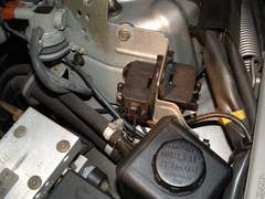
Locate the diagnostic service interface. This is a little black plastic box located near the shock tower on the driver’s side engine bay. This varies slightly from model to model. The protective cover must first be removed.
Turn the ignition switch to the ON position, but do not start the car.
Locate the jumper lead (the plug stores in a pocket in the cover) and insert it into the socket number 6. Press the diagnostic button on the interface for about a second and a half, about the time required to say “Volvo Corporation”.
The LED will begin flashing, with the flashes representing diagnostic codes. Flashes are presented in three groups of flashes (approximately 0.5 seconds), separated by a slightly longer interval: first, second and third, representing the first, second and third digit of a three-digit code. Have a look at this short video showing the LED flashing.
If the code presented is 1-1-1, that means that the register is empty and there are no fault codes stored. A non-1-1-1 fault code represents a specific trouble, which can be decoded using the associated table.
After a fault code has been recorded, press the button again, saying “Volvo Corporation”.
The next code is displayed or, if there are no more codes, the first code is displayed again.
When all of the codes have been recorded, the buffer can be erased by first pressing and holding the button for five seconds and then releasing it.
After a brief pause, the LED should again light. Press and hold the button for an additional five seconds and then release. The LED should go out.
System Overview - System Components
The fuel system consists of an air mass meter, commonly referred to as MAF sensor, an oxygen sensor, a throttle body, fuel injectors (one per cylinder) and a catalytic converter.
The Mass Air Flow (MAF and often referred to as air mass meter) is responsible for measuring instantaneous airflow into the engine. In LH, the MAF consists of a wire that is heated with an electrical current and cooled in proportion to the air flowing over it. The sensor measures how much power is required to keep the hot wire at its prescribed temperature and that tells the fuel management system how much air is flowing into the engine. The wire should remain clean so, when the engine is turned off a relay is activated for a preset time and the wire is super heated to burn off any dirt.
The Heated Oxygen Sensor (H02S), located in the hot exhaust gas stream, analyses the gas content of the exhaust and reports the content to the control computer. This sensor operates only above a certain temperature and therefore its readings are disregarded for a short period of time following engine startup.
The Throttle Body is the fuel injection equivalent of the throttle in a carburetor. It is responsible for regulating the flow of air (and therefore the flow of fuel) into the engine. The idle switch signals the computer when the throttle is closed and the Idle Air Control (IAC) valve should be activated.
The Idle Air Control valve is an electronically controlled valve that allows relatively small amounts of intake air into the engine. This is used only when the idle switch on the throttle body signals that the throttle is closed. This system allows the engine control computer to maintain a precise idle speed regardless of engine condition and load.
The Throttle Position Sensor, or TPS, is located on the throttle body at one end of the throttle shaft. It signals the computer when the throttle is either closed (IAC can be activated) or fully open.
The Fuel Injectors, not surprisingly, inject fuel into the stream of intake air, normally immediately before the intake valve.
The Fuel Pressure Regulator maintains a precise fuel pressure on the fuel rail supplying the injectors. The fuel pump attempts to deliver fuel at a fixed rate, so the excess is returned to the fuel tank via a dedicated return line.
The Catalytic Converter is an element of the exhaust system located relatively close to the engine. It is responsible for breaking down the unwanted by-products of combustion, such as carbon monoxide, hydrocarbons and nitrogen oxides.
The Coolant Temperature Sensor monitors the temperature of the engine coolant and thus the operating temperature of the engine.
The Engine Speed Sensor (ESS), Impulse Sensor or RPM sensor is a sensor that actually determines the position of the crankshaft as it rotates. The sensor is more correctly named the Crankshaft Position Sensor, as speed can be derived from angle, but angle cannot be derived from speed. This sensor is responsible for synchronising fuel and ignition.